"섬유광통신"의 두 판 사이의 차이
(새 문서: 광통신 <ol> <li>인터넷에서 ONU <ol> <li>EPON ONU transciever module <ol> <li>SC connector <gallery> image:ont_megapass_023.jpg image:ont_megapass_024.jpg image:ont_megapass_02...) |
잔글 |
||
| (같은 사용자의 중간 판 3개는 보이지 않습니다) | |||
| 1번째 줄: | 1번째 줄: | ||
| − | + | 섬유광통신 | |
<ol> | <ol> | ||
| − | <li> | + | <li> [[전자부품]] |
<ol> | <ol> | ||
| − | <li> | + | <li>광 |
<ol> | <ol> | ||
| − | <li>SC connector | + | <li> [[섬유광통신]] - 이 페이지 |
| + | <li> [[광섬유]] | ||
| + | </ol> | ||
| + | <li>참고 | ||
| + | <ol> | ||
| + | <li> [[본딩 캐필러리]] | ||
| + | </ol> | ||
| + | </ol> | ||
| + | <li>EPON ONT(Ethernet Passive Optical Network, Optical Network Terminal)에서 | ||
| + | <ol> | ||
| + | <li> EPON ONT [[텔리언 EP-3201N]] 에서 | ||
| + | <ol> | ||
| + | <li>ONU; optical network unit로 사용되는, EPON ONU transciever module(송수신 모듈) | ||
| + | <li>(아마 KT용) 가정용 광 라우터 보드에서 | ||
| + | <gallery> | ||
| + | image:ont_megapass_024.jpg | eoptolink회사의 EOLF-GEU-10, Tx 1310nm, Rx 1490nm, 10km용 | ||
| + | image:ont_megapass_025.jpg | 모듈을 PCB에서 뜯어내기 위해 보드를 갈아냄 | ||
| + | </gallery> | ||
| + | <li>모듈을 정면으로 볼 때, SC connector 접속구 | ||
<gallery> | <gallery> | ||
image:ont_megapass_023.jpg | image:ont_megapass_023.jpg | ||
| − | + | </gallery> | |
| − | + | <li>모듈 내부 | |
| + | <gallery> | ||
image:ont_megapass_026.jpg | image:ont_megapass_026.jpg | ||
image:ont_megapass_027.jpg | image:ont_megapass_027.jpg | ||
| + | </gallery> | ||
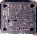
| + | <li>레이저 다이오드(4선;출력 및 출력 피드백용) 및 포토 다이오드(2선) 모듈, FP-LD-LU 1310 1.25G 3.3V, Fabry-Perot 타입 LD | ||
| + | <gallery> | ||
image:ont_megapass_028.jpg | image:ont_megapass_028.jpg | ||
image:ont_megapass_029.jpg | image:ont_megapass_029.jpg | ||
image:ont_megapass_030.jpg | image:ont_megapass_030.jpg | ||
| − | |||
</gallery> | </gallery> | ||
| − | <li>접속구 | + | <li>SC connector 접속구 |
<gallery> | <gallery> | ||
| − | image:ont_megapass_032.jpg | + | image:ont_megapass_032.jpg | ferrule을 빼낸 후 |
image:ont_megapass_033.jpg | image:ont_megapass_033.jpg | ||
| + | </gallery> | ||
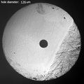
| + | <li>ferrule 끝단 | ||
| + | <gallery> | ||
| + | image:ont_megapass_031.jpg | inner frame | ||
image:ont_megapass_034.jpg | image:ont_megapass_034.jpg | ||
| − | image:ont_megapass_035.jpg | + | image:ont_megapass_035.jpg | 홀 직경 126um |
</gallery> | </gallery> | ||
</ol> | </ol> | ||
</ol> | </ol> | ||
| − | <li>OmniBER | + | <li> [[OmniBER 725, Optical Interface]]에서 |
<ol> | <ol> | ||
<li>보드 외관 | <li>보드 외관 | ||
<gallery> | <gallery> | ||
| − | image:j1409a00_021.jpg|커넥터 3개. 3개의 모듈이 있다. | + | image:j1409a00_021.jpg | 커넥터 3개. 3개의 모듈이 있다. |
image:j1409a00_010.jpg | image:j1409a00_010.jpg | ||
</gallery> | </gallery> | ||
<li>광 커넥터(FC connector에서 FC/PC)를 받아들이는 소켓(왜냐면 계측기이므로) | <li>광 커넥터(FC connector에서 FC/PC)를 받아들이는 소켓(왜냐면 계측기이므로) | ||
| + | <ol> | ||
| + | <li>외관 | ||
<gallery> | <gallery> | ||
image:j1409a00_025_028.jpg | image:j1409a00_025_028.jpg | ||
| 40번째 줄: | 67번째 줄: | ||
image:j1409a00_025_031.jpg | image:j1409a00_025_031.jpg | ||
</gallery> | </gallery> | ||
| + | <li>FC connector 접촉면 | ||
| + | <gallery> | ||
| + | image:j1409a00_025_030_001.jpg | ||
| + | image:j1409a00_025_030_002.jpg | ||
| + | image:j1409a00_025_030_003.jpg | 광섬유 코어직경 약 63um | ||
| + | </gallery> | ||
| + | <li>여기와 연결된 오렌지색 광섬유 | ||
| + | <gallery> | ||
| + | image:j1409a00_025_043_001.jpg | ||
| + | image:j1409a00_025_043_002.jpg | 코어 직경 약 60um(정확히 62.5um) | ||
| + | image:j1409a00_025_043_003.jpg | ||
| + | </gallery> | ||
| + | </ol> | ||
<li>Rx/Tx 모듈 | <li>Rx/Tx 모듈 | ||
| + | <ol> | ||
| + | <li>3개 | ||
<gallery> | <gallery> | ||
image:j1409a00_025_026.jpg | image:j1409a00_025_026.jpg | ||
image:j1409a00_025_027.jpg | image:j1409a00_025_027.jpg | ||
</gallery> | </gallery> | ||
| − | <li>Fiber Optic | + | <li>2개 있는 Fiber Optic Transmitter Module [[OmniBER 725, 광섬유 송신모듈]] 에서 자세히 분석함. |
<ol> | <ol> | ||
| − | <li> | + | <li>1310nm |
| − | + | <li>1550nm | |
| − | |||
| − | |||
| − | |||
| − | |||
| − | |||
| − | |||
| − | |||
| − | |||
| − | |||
| − | |||
| − | |||
| − | |||
| − | |||
| − | |||
| − | |||
| − | |||
| − | |||
| − | |||
| − | |||
| − | |||
| − | |||
| − | |||
| − | |||
| − | |||
| − | |||
| − | |||
| − | |||
| − | |||
| − | |||
| − | |||
| − | |||
| − | |||
| − | |||
| − | |||
| − | |||
| − | |||
| − | |||
| − | |||
| − | |||
| − | |||
| − | |||
| − | |||
| − | |||
| − | |||
| − | |||
| − | |||
| − | <li> | ||
| − | |||
| − | |||
| − | |||
| − | |||
| − | |||
| − | |||
| − | |||
| − | |||
</ol> | </ol> | ||
| − | <li>Fiber Optic | + | <li>1개 있는 Fiber Optic Receive Module [[OmniBER 725, 광섬유 수신모듈]] 에서 자세히 분석함. |
| − | |||
| − | |||
| − | |||
| − | |||
| − | |||
<ol> | <ol> | ||
| − | <li> | + | <li>1200~1600nm |
| − | |||
| − | |||
</ol> | </ol> | ||
| − | |||
| − | |||
| − | |||
| − | |||
| − | |||
| − | |||
| − | |||
| − | |||
| − | |||
| − | |||
| − | |||
| − | |||
| − | |||
| − | |||
| − | |||
| − | |||
| − | |||
| − | |||
| − | |||
| − | |||
| − | |||
| − | |||
| − | |||
| − | |||
| − | |||
| − | |||
| − | |||
| − | |||
| − | |||
| − | |||
| − | |||
| − | |||
| − | |||
| − | |||
| − | |||
| − | |||
| − | |||
| − | |||
| − | |||
| − | |||
| − | |||
| − | |||
| − | |||
| − | |||
| − | |||
| − | |||
| − | |||
| − | |||
| − | |||
| − | |||
| − | |||
| − | |||
| − | |||
| − | |||
| − | |||
| − | |||
| − | |||
| − | |||
| − | |||
| − | |||
| − | |||
| − | |||
| − | |||
| − | |||
| − | |||
| − | |||
| − | |||
| − | |||
| − | |||
| − | |||
| − | |||
| − | |||
| − | |||
| − | |||
| − | |||
| − | |||
| − | |||
| − | |||
| − | |||
| − | |||
| − | |||
| − | |||
| − | |||
| − | |||
| − | |||
| − | |||
| − | |||
| − | |||
| − | |||
| − | |||
| − | |||
</ol> | </ol> | ||
</ol> | </ol> | ||
| 217번째 줄: | 106번째 줄: | ||
image:4339b01_003.jpg | image:4339b01_003.jpg | ||
image:4339b01_004.jpg | image:4339b01_004.jpg | ||
| − | image:4339b01_008.jpg | + | image:4339b01_008.jpg | fiber optic connection, HFBR-1521 Tx, HFBR-2521 Rx, 600nm, 5Mbd |
</gallery> | </gallery> | ||
</ol> | </ol> | ||
<li>HP 3458A DMM - Avago's Versatile Link cables로 2Mbit bidirectional UART optical link 연결 | <li>HP 3458A DMM - Avago's Versatile Link cables로 2Mbit bidirectional UART optical link 연결 | ||
<gallery> | <gallery> | ||
| − | image:3458a01_032.jpg | + | image:3458a01_032.jpg | 파워와 GPIB부와의 통신은 아이솔레이션을 위해 광케이블로 통신 |
| − | image:3458a01_033.jpg | + | image:3458a01_033.jpg | 파워 |
| − | image:3458a01_034.jpg| | + | image:3458a01_034.jpg | 디지털 처리부 |
</gallery> | </gallery> | ||
</ol> | </ol> | ||
| 235번째 줄: | 124번째 줄: | ||
image:spdif1_003.jpg | image:spdif1_003.jpg | ||
image:spdif1_004.jpg | image:spdif1_004.jpg | ||
| − | image:spdif1_005.jpg|포토다이오드 | + | image:spdif1_005.jpg | 포토다이오드 |
| − | image:spdif1_006.jpg|수신 IC | + | image:spdif1_006.jpg | 수신 IC |
| + | </gallery> | ||
| + | <li> [[FFH-DV550]] LG 하이파이오디오 | ||
| + | <ol> | ||
| + | <li> [[섬유광통신]]용 광디지털 음성출력 단자, S/PDIF(Sony/Philips Digital Interface Format) 부근 | ||
| + | <gallery> | ||
| + | image:hifi01_078.jpg | S-VIDEO OUT, VIDEO SELECT - PAL NTSC AUTO, OPTICAL OUT | ||
| + | image:hifi01_083.jpg | 5V, data, gnd | ||
| + | </gallery> | ||
| + | <li> [[IR LED]] 및 드라이브 IC | ||
| + | <gallery> | ||
| + | image:hifi01_079.jpg | ||
| + | image:hifi01_080.jpg | ||
| + | image:hifi01_080_001.jpg | ||
| + | image:hifi01_080_002.jpg | ||
</gallery> | </gallery> | ||
| + | </ol> | ||
</ol> | </ol> | ||
</ol> | </ol> | ||
2023년 12월 27일 (수) 23:06 기준 최신판
섬유광통신
- 전자부품
- EPON ONT(Ethernet Passive Optical Network, Optical Network Terminal)에서
- EPON ONT 텔리언 EP-3201N 에서
- ONU; optical network unit로 사용되는, EPON ONU transciever module(송수신 모듈)
- (아마 KT용) 가정용 광 라우터 보드에서
- 모듈을 정면으로 볼 때, SC connector 접속구
- 모듈 내부
- 레이저 다이오드(4선;출력 및 출력 피드백용) 및 포토 다이오드(2선) 모듈, FP-LD-LU 1310 1.25G 3.3V, Fabry-Perot 타입 LD
- SC connector 접속구
- ferrule 끝단
- EPON ONT 텔리언 EP-3201N 에서
- OmniBER 725, Optical Interface에서
- 보드 외관
- 광 커넥터(FC connector에서 FC/PC)를 받아들이는 소켓(왜냐면 계측기이므로)
- 외관
- FC connector 접촉면
- 여기와 연결된 오렌지색 광섬유
- 외관
- Rx/Tx 모듈
- 3개
- 2개 있는 Fiber Optic Transmitter Module OmniBER 725, 광섬유 송신모듈 에서 자세히 분석함.
- 1310nm
- 1550nm
- 1개 있는 Fiber Optic Receive Module OmniBER 725, 광섬유 수신모듈 에서 자세히 분석함.
- 1200~1600nm
- 3개
- 보드 외관
- 계측기내 광통신
- 4339B High Resistance Meter에서
- 측정 메인보드에서 측정결과(ADC 신호)를 광통신으로 CPU보드로 보낸다.
- 측정 메인보드에서 측정결과(ADC 신호)를 광통신으로 CPU보드로 보낸다.
- HP 3458A DMM - Avago's Versatile Link cables로 2Mbit bidirectional UART optical link 연결
- 4339B High Resistance Meter에서
- S/PDIF (Sony/Philips Digital Interface Format)


